
BPS : 115200
DE1-SoC Board default Frequency : 50Mhz [20ns]
1/115200 = 0.00000868s = 0.00868ms = 8.68us = 8680ns [1bit]
need to maintain 434 cycles to make 8680ns.

// 434 counter = 8680ns

reg [3:0] cst; //idle ~ stop_1, 12 state
reg [3:0] nst;
reg [8:0] clk_count; // 512, 9bit

always @(posedge clk, negedge reset_n) begin
    if(!reset_n) begin // active low
        clk_count <= 0; // reset clk count
    else if(clk_count == 433) begin
        clk_count <= 0; // clear the count
    else begin
        clk_count <= clk_count + 1; // count one by one
    end
end
Uart 통신은 Asychronous communication(비동기식) 이기 때문에 Tx 와 Rx 가 Clock Signal 을 공유하지 않는다. 그렇기 때문에 START Bit 와 STOP Bit 로 송수신의 시작과 끝을 파악하는 Data Frame 이 필요하다.
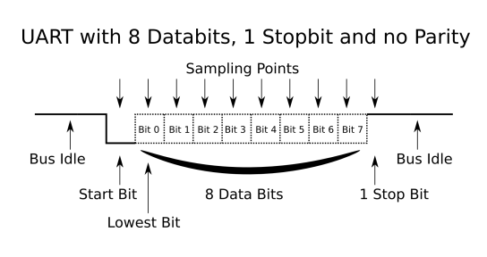
UART Data Frame 은 기본적으로 IDLE = 1, START = 0, STOP = 1 의 값을 가진다.

실제 Data 값과 반대로 Uart Data Frame 은 LSB First 이다.
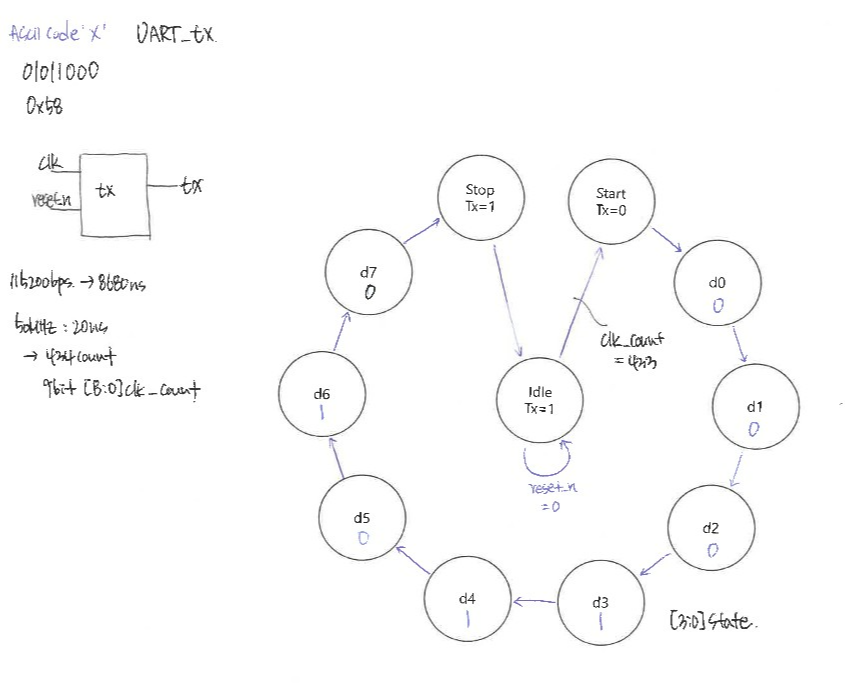
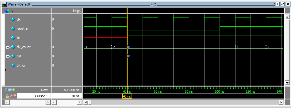
Date Frame 을 바탕으로 FSM 을 설계해야 한다. 처음에 115200 bps 를 만족하도록 434 clock counter 를 설계했다. IDLE 에서 clk_count 가 433 이 만족하면, clk_count 는 다시 0 부터 count 를 시작하고, IDLE 은 START 로, Tx Output 은 1 에서 0 으로 떨어진다. 각 Output 은 State 만을 참조하므로 Moore Machine 을 따른다.
module simple_uart_tx (
    input   clk     ,
    input   reset_n ,
    output  tx
);

    localparam idle   = 0  ,
               start  = 1  ,
               D0     = 2  ,
               D1     = 3  ,
               D2     = 4  ,
               D3     = 5  ,
               D4     = 6  ,
               D5     = 7  ,
               D6     = 8  ,
               D7     = 9  ,
               stop   = 10 ,
               stop_1 = 11 ;

    reg r_tx;
    reg [3:0] cst;
    reg [3:0] nst;
    reg [8:0] clk_count = 9'd0;

    wire bit_clr = (clk_count == 433); // using in control signal

//counter
    always@(posedge clk, negedge reset_n)begin
    if(!reset_n)begin // active low
        clk_count <= 9'b0;
        cst <= idle;
    end
    else if (bit_clr)begin
        clk_count <= 9'b0;
        cst <= nst;
    end
    else
        clk_count <= clk_count + 9'b1;
    end

    always@(*)begin
        case(cst)
            idle    : nst = start ;
            start   : nst = D0    ;
            D0      : nst = D1    ;
            D1      : nst = D2    ;
            D2      : nst = D3    ;
            D3      : nst = D4    ;
            D4      : nst = D5    ;
            D5      : nst = D6    ;
            D6      : nst = D7    ;
            D7      : nst = stop  ;
            stop    : nst = idle  ;
            default : nst = start ;
        endcase
    end

    always@(*)begin // ASCII code 'X'
        case(cst)
            idle    : r_tx = 1'b1 ;
            start   : r_tx = 1'b0 ;
            D0      : r_tx = 1'b0 ;
            D1      : r_tx = 1'b0 ;
            D2      : r_tx = 1'b0 ;
            D3      : r_tx = 1'b1 ;
            D4      : r_tx = 1'b1 ;
            D5      : r_tx = 1'b0 ;
            D6      : r_tx = 1'b1 ;
            D7      : r_tx = 1'b0 ;
            stop    : r_tx = 1'b1 ;
            default : r_tx = 1'b1 ;
        endcase
    end

    assign tx = r_tx;

endmodule


idle, strat, data 8bit, stop_0, stop_1 : 8680ns X 12 = 104160ns
115200/12 = 9600 Baud Rate.
Tera-Term 과 연결하여 실제로 ACSII 'X' 값이 제대로 전송되는지 확인했다.
'[Harman] 반도체 설계 > Quartus' 카테고리의 다른 글
| Quartus II Project - notes [2] (0) | 2023.08.13 |
|---|---|
| Quartus II project - notes [1] (0) | 2023.08.12 |
| Quartus II Project - fnd counter (2) | 2023.08.11 |
| Quartus II Project - adder, mult4x4 (0) | 2023.07.27 |
| Quartus II Project - mux4, shifter (0) | 2023.07.27 |


