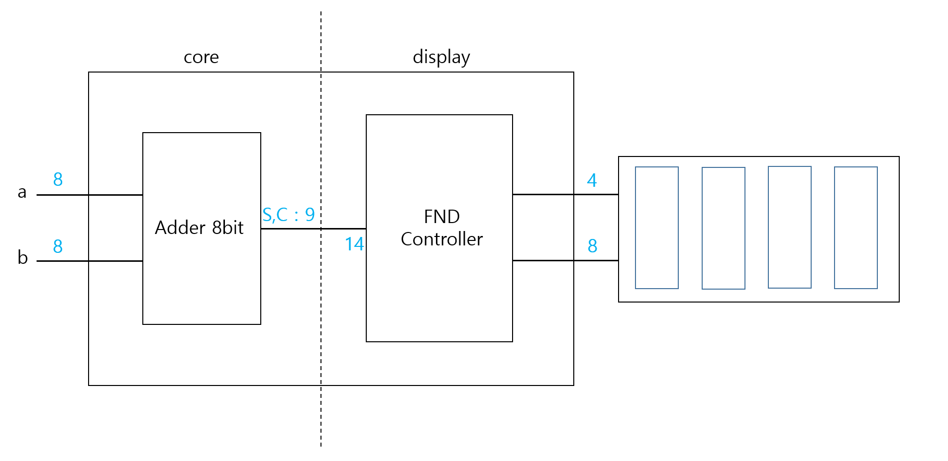
[1] 14bit 의 입력을 받은 FndController 는 0 ~ 9999 까지의 수를 표현했다. 이번에는 FndController 와 Adder 8 bit 를 활용해서 8 bit 가산기를 설계하려고 한다.
[Vivado] 03. Adder_8bit
Half Adder. module half_adder ( input i_a, input i_b, output o_sum, output o_carry ); assign o_sum = i_a ^ i_b; assign o_carry = i_a & i_b; endmodule Full Adder 1 bit. module full_adder_1bit ( input i_a, input i_b, input i_cin, output o_sum, output o_carry
lrsfe.tistory.com
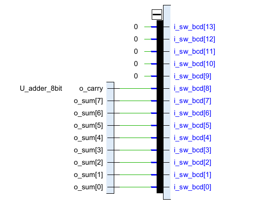
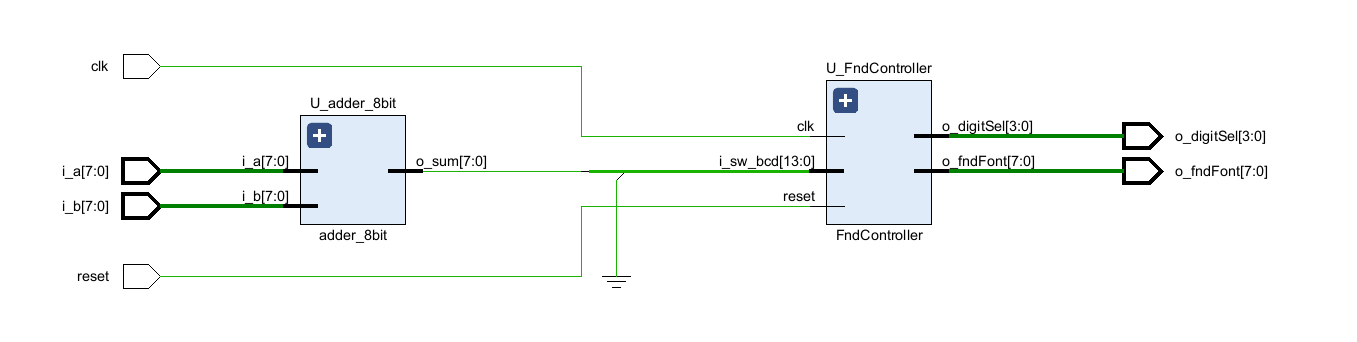
[2] a 8bit, b 8bit 를 더해서 {Carry 1bit, Sum 8 bit} = 9 bit, 나머지 5 bit 는 0 으로 채워서 [1] 과 동일하게 14 bit 를 만들려고 한다. FndController 의 입력이 14 bit 이기 때문에 8 bit 가산기의 결과가 {Carry, Sum} 로 9 bit 라도 0 을 추가해서 14 bit 를 만들어 준다.
`timescale 1ns / 1ps

module Calculator_8bit(
    input clk,
    input reset,
    input [7:0] i_a,
    input [7:0] i_b,
    output [3:0] o_digitSel,
    output [7:0] o_fndFont
    );

    wire [7:0] w_sum;
    wire w_carry;
    wire w_zero;

    adder_8bit U_adder_8bit(
        .i_a(i_a),
        .i_b(i_b),
        .o_sum(w_sum),
        .o_carry(w_carry)
    );

    assign w_zero = {5'b00000, w_carry, w_sum};

    FndController U_FndController(
        .clk(clk),
        .reset(reset),
        .i_sw_bcd(w_zero),
        .o_digitSel(o_digitSel),
        .o_fndFont(o_fndFont)
    );

endmodule
`timescale 1ns / 1ps
module Calculator_8bit(
input clk,
input reset,
input [7:0] i_a,
input [7:0] i_b,
output [3:0] o_digitSel,
output [7:0] o_fndFont
);
wire [8:0] w_sum;
adder_8bit U_adder_8bit(
.i_a(i_a),
.i_b(i_b),
.o_sum(w_sum[7:0]),
.o_carry(w_sum[8])
);
FndController U_FndController(
.clk(clk),
.reset(reset),
.i_sw_bcd({5'b0, w_sum}),
.o_digitSel(o_digitSel),
.o_fndFont(o_fndFont)
);
endmodule'[Harman] 반도체 설계 > Vivado' 카테고리의 다른 글
| [Vivado] 06. Calculator 8bit, FSM StopWatch 0.1s UpCount (0) | 2023.08.05 |
|---|---|
| [Vivado] 05. Finite State Machine LED (0) | 2023.08.05 |
| [Vivado] 03. Adder 8bit (0) | 2023.08.05 |
| [Vivado] 02. FndController, Counter, DigitSplitter, clkDivider (0) | 2023.08.05 |
| [Vivado] 01. FndController, 2x4_Decoder (0) | 2023.08.04 |


