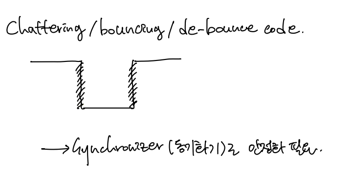
Data 가 변하는 과정에서 Chattering, Bouncing 등이 발생할 수도 있으며 이럴 때, 입력 값이 0 인지 1 인지 정확하게 확인할 수 없는 Meta Stable 상태가 되고 오류를 발생시킨다. 이는 동기화(Synchronize, D_FF) 를 통해 해결할 수 있다.
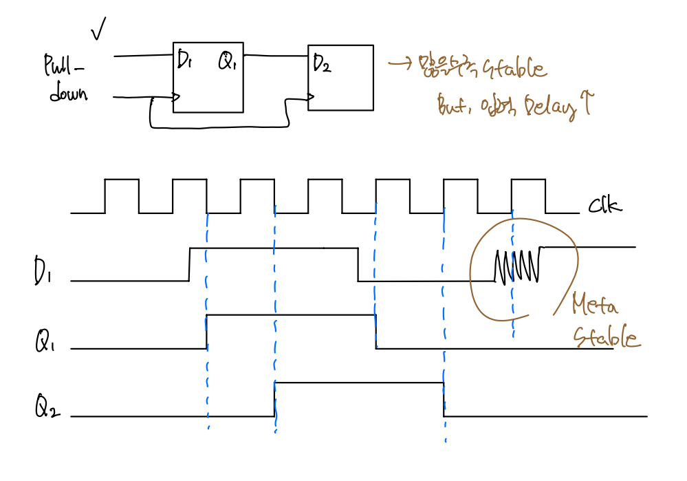
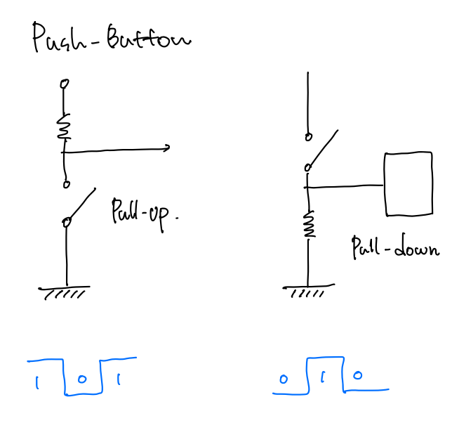
D_FF 가 많으면 많을수록 System 은 더 안정된다. 하지만 그 만큼 입력 Delay 가 길어지는 단점도 있다. Pull - Down 장치로 PB 를 Arbitrary Time 동안 눌렀을 때, 1 이 정확하게 1 period 만큼만 발생하도록 설계하려고 한다.
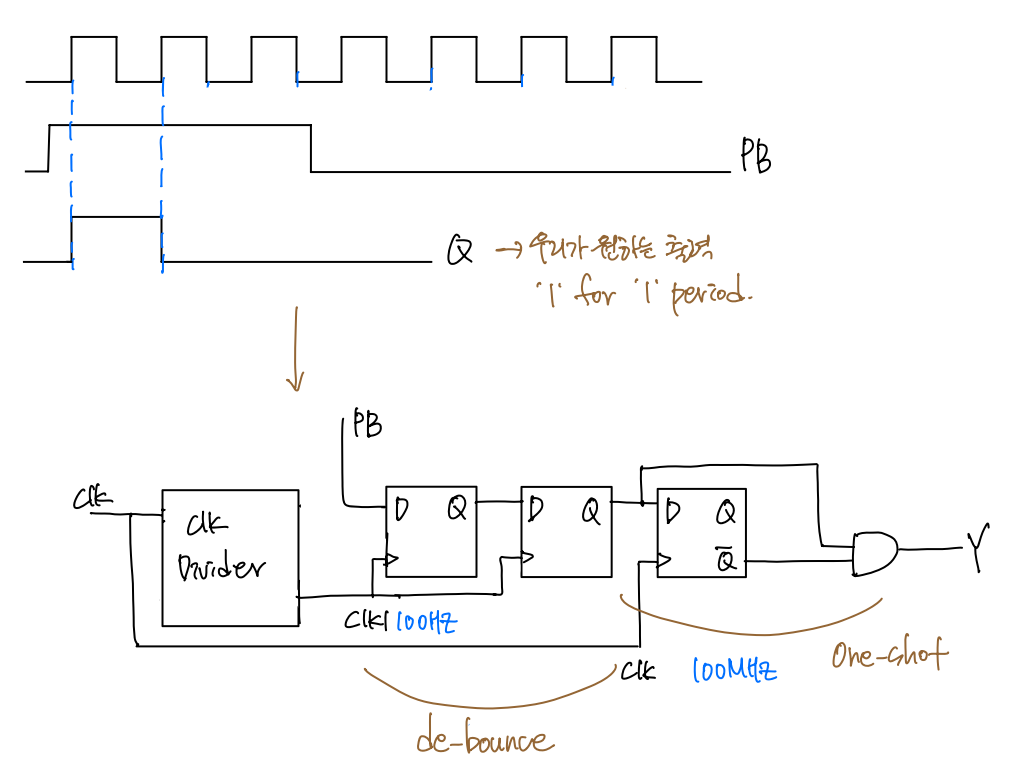
[1] Switch[0], [1] 대신 PushButton (runstop, clear) 을 사용하기 위해서는 D_FF 를 활용한 Synchronizer 가 필요하다. 안정화된 PB Input 과 '1' for '1' period 를 출력하기 위해 clkDivider, de-bounce circuit, one-shot circuit 을 설계해야 한다.
Step 1. clkDivider : Time 과 관련된 모든 것들은 Clock 으로 제어할 수 있다. 적절한 출력 값을 확인하기 위해 100Mhz 의 기본 주파수를 100hz 까지 낮춘다.
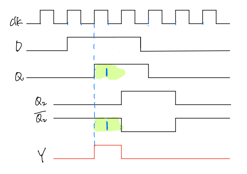
Step 2. de-bounce circuit : D_FF1, D_FF2 를 거치면서 Input D (PB) 는 Stable 한 상태가 된다. (Synchronize, 동기화)
Step 3. one-shot circuit : 출력 '1' for '1' period 는 Q1 과 Q2' 의 논리곱으로 나타난다. One-Shot Circuit 이 100hz 의 clk 를 받을 경우, 출력 Q2' 가 밀린다. 따라서, clkDivider 를 거치지 않고 100Mhz 의 clk 을 그대로 받아 Q2' 값을 출력한다.
`timescale 1ns / 1ps

module PushButton_Oneshot(
    input clk,
    input i_pb,
    input reset,
    output o_pb
    );

    // clkDivider_100hz

    reg r_clk_100hz;
    reg [31:0] r_counter = 0;

    always@(posedge clk, posedge reset) begin // Divider 100hz
        if(reset) begin
            r_counter <= 0;
        end
        else begin
            if(r_counter == 500_000 - 1) begin //duty cycle 50%
                r_counter = 0;
                r_clk_100hz <= ~r_clk_100hz;
            end
            else begin
                r_counter <= r_counter + 1;
            end
        end
    end

    //de-bounce

    reg [1:0] r_debounce = 2'b00; //DFF

    always @(posedge r_clk_100hz, posedge reset) begin
        if(reset) begin
            r_debounce <= 2'b00;
        end
        else begin
            r_debounce[0] <= i_pb;
            r_debounce[1] <= r_debounce[0];
        end
    end

    // one shot

    reg r_oneshot = 1'b0;

    always@(posedge clk, posedge reset) begin
        if(reset) begin
            r_oneshot <= 1'b0;
        end
        else begin
            r_oneshot <= r_debounce[1];
        end
    end

    assign o_pb = r_debounce[1] & ~r_oneshot;

endmodule
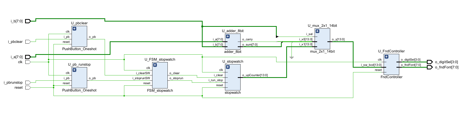
[2] PushButton 에 대한 '1' for '1' period 를 설계했다. 기존의 i_a[0] Switch 는 PushButton_runstop 으로, i_a[1] Switch 는 PushButton_clear 로 대체된다.
`timescale 1ns / 1ps

module Calculator_8bit_PB_FSM_stopwatch(
    input clk,
    input reset,
    input [7:0] i_a,
    input [7:0] i_b,
    input i_pbrunstop,
    input i_pbclear,
    output [3:0] o_digitSel,
    output [7:0] o_fndFont
    );

    wire [8:0] w_sum;
    wire w_stoprun, w_clear;
    wire [13:0] w_stopwatchValue, w_FndsourceValue;
    wire w_pbrunstop, w_pbclear;

    PushButton_Oneshot U_pb_runstop(
        .clk(clk),
        .i_pb(i_pbrunstop),
        .reset(reset),
        .o_pb(w_pbrunstop)
    );

    PushButton_Oneshot U_pbclear(
        .clk(clk),
        .i_pb(i_pbclear),
        .reset(reset),
        .o_pb(w_pbclear)
    );

    FSM_stopwatch U_FSM_stopwatch(
        .clk(clk),
        .reset(reset),
        .i_stoprunSW(w_pbrunstop),
        .i_clearSW(w_pbclear),
        .o_stoprun(w_stoprun),
        .o_clear(w_clear)
    );

    stopwatch U_stopwatch(
        .clk(clk),
        .reset(reset),
        .i_run_stop(w_stoprun),
        .i_clear(w_clear),
        .o_upCounter(w_stopwatchValue)
    );

    adder_8bit U_adder_8bit(
        .i_a(i_a),
        .i_b(i_b),
        .o_sum(w_sum[7:0]),
        .o_carry(w_sum[8])
    );

    mux_2x1_14bit U_mux_2x1_14bit(
        .i_sel(i_b[7]),
        .i_x0({5'b0, w_sum}),
        .i_x1(w_stopwatchValue),
        .o_y(w_FndsourceValue)
    );

    FndController U_FndController(
        .clk(clk),
        .reset(reset),
        .i_sw_bcd(w_FndsourceValue),
        .o_digitSel(o_digitSel),
        .o_fndFont(o_fndFont)
    );

endmodule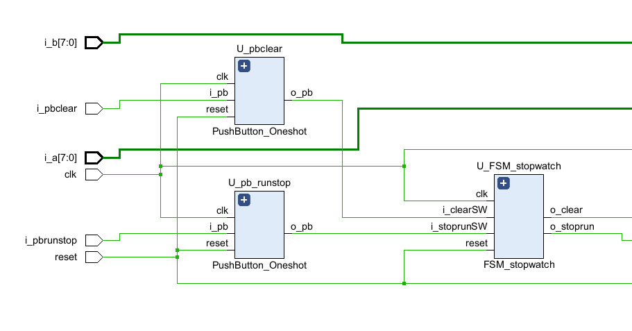
'[Harman] 반도체 설계 > Vivado' 카테고리의 다른 글
| [Vivado] 0X. Source Code (0) | 2023.08.05 |
|---|---|
| [Vivado] 06. Calculator 8bit, FSM StopWatch 0.1s UpCount (0) | 2023.08.05 |
| [Vivado] 05. Finite State Machine LED (0) | 2023.08.05 |
| [Vivado] 04. FndController, Adder 8bit (0) | 2023.08.05 |
| [Vivado] 03. Adder 8bit (0) | 2023.08.05 |


